Light Modulation
G5UJ The Radio Constructor, February, 1960.
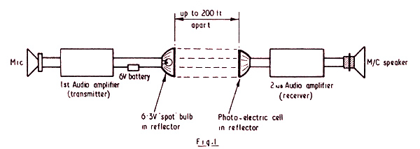
An interesting experiment was carried out recently by a friend of the writer. Briefly, it took the form of light modulation. The equipment needed (as a glance at Fig. 1 will show) is quite simple. A carbon, or similar microphone, is fed into a small two- or three-watt audio amplifier, which might well consist of an ordinary domestic receiver the output being taken through a standard speaker transformer.
Light Modulation System.
The 3Ω secondary of this transformer has connected across it a 6.3 Volt spotlight bulb, together with a 6 Volt battery. The metal reflectors are removed from two electric hand torches, and placed some distance apart, facing each other. The optimum distance between the two reflectors must be found by experiment, but 20 to 30 feet was quite satisfactory in this instance.
As will be noted from the diagram at Fig. 1, the 6.3 Volt bulb is mounted in one reflector connected in the output of the first, or Transmitter Amplifier, whilst a photo-electric cell, almost any type, or a photo-transistor OCP71, is mounted in the other reflector. Output from the PE cell is, of course, fed into the grid circuit of a second or Receiver Amplifier, output then being taken in the normal way through a moving coil speaker.
Quite good speech quality was obtained even at distances up to 200 feet, but great care is necessary in placing the two reflectors in exact alignment.
It may also be desirable to try several different spotlight bulbs, as not all bulbs will be found suitable. Car head and side-lamp bulbs will not be found suitable as a rule, due to time lag in the filament when following fluctuations of speech, etc. In passing, it should be stressed that direct light from ordinary domestic AC mains lamps must not be allowed to impinge on the PE cell, or AC modulation will result!
Though perhaps not an original idea, the foregoing does seem to offer a wide scope for further experiment.
|