Communication by Modulated Arc Beam
H S King The Radio Constructor, February, 1966.
We have previously published articles on modulated light systems, these all employing transmitting lamps whose filament current was modulated by the audio signal to be transmitted. A disadvantage with all these systems has been given by the thermal inertia of the filament, which limits the maximum frequency the system can handle. Our contributor has overcome this problem by using an arc lamp as light source, whereupon a maximum frequency of 10 kHz is capable of being transmitted. Also, the arc lamp provides an intense light source of very small area, enabling transmissions to be received over long distances. Tests with the prototype resulted in clear reception of the modulated beam at a distance of nearly a quarter of a mile in daylight.
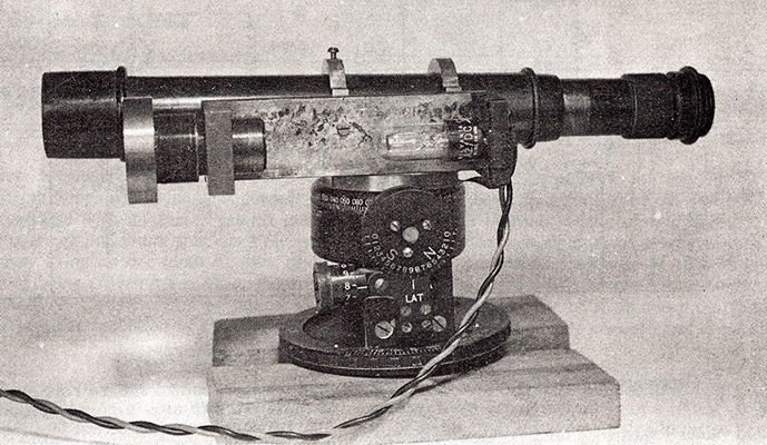
The Sylvania arc lamp fitted to an ex-WD torpedo directing telescope. The telescope is used merely to provide a convenient mounting, together with sighting facilities. The arc lamp is to the right on the bracket, with the single lens which concentrates its beam at the left. Connection to the lamp is via the twin flex leading from its base.
Having experimented with various published and unpublished methods of modulating a light beam it was concluded that the incandescent filament is not the best light source to modulate.
Both mains and battery bulbs suffer from the obvious disadvantages of narrow bandwidth due to thermal inertia, and low beam concentration due to the large size of the source.
A pea bulb may be connected directly to the speaker transformer secondary of a 10 Watt amplifier or a mains bulb into the anode circuit of a power amplifier and speech which is just about intelligible may be received on a photocell a few feet away using a simple lens system. Greater distances may be obtained using a more complex lens system but the better the transmitting lens the smaller the area of the filament which is actually employed.
If the light source can be concentrated into the smallest possible area a greater proportion of the light produced can then be put into the beam. This principle has been the main aim in the design of film projectors. One of the most concentrated light sources is the arc lamp but it was decided not to attempt the modulation of the open arc. However when attention was drawn to an enclosed arc which could be maintained in the anode circuit of a modest power valve it was decided that this method had attractions for the amateur.
Arc Lamp Transmitter
The Sylvania Concentrated-Arc Lamp type A2 was therefore made the subject for experiment in the light beam transmitter. A disadvantage is the price, which is rather high for the amateur, but this is possibly due to the small demand. The range of Sylvania lamps includes many at considerably higher prices but the A2 seems the most suitable for amateur experiments. The A2 lamp is quite small physically, as may be seen from the appropriate illustration, and it requires a maintaining voltage of 38 Volts when 55mA is passed. This may be obtained in the anode circuit of a 6L6G but arrangements must be made to strike the arc as described later. The lamp electrodes consist of a small disc, the anode, with a central hole through which projects a fine wire which is the cathode. The arc strikes between the wire and the anode and has a tendency to wander round the hole in the disc, thus disturbing the beam direction slightly. However, the light source is extremely small and, by using a simple 1 inch convex lens with a focal length of 2 inches, the light can be seen shining very brightly even in daylight at a distance of a quarter of a mile. In the photograph the lamp is shown mounted upon an old astro compass adapted to take an ex-naval torpedo directing telescope. This telescope, although short of a lens and thus giving a magnification of unity, does possess cross-wires which make alignment of the beam on to the receiver fairly easy. At a distance of one eighth of a mile the beam spreads to about three feet diameter.
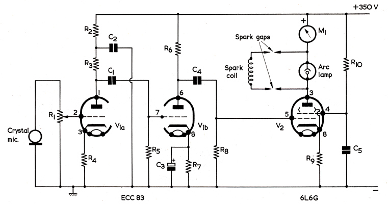
Fig. 1. The circuit of the light beam transmitter.
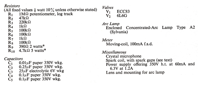
Transmitter Components list.
* May require adjustment to provide correct arc current.
The transmitter is quite straightforward and capable of many variations. The circuit, shown in Fig. 1, was built up from first principles as an exercise for school pupils and has no refinements. The HT voltage, screen and cathode resistors of the 6L6G should be adjusted to give an anode current of 50 to 55mA. The valve can be triode-connected if desired. A crystal microphone has been used successfully. Alternatively, of course, a signal from a radio or other source can be applied, and this makes adjustment easier at the receiver end.
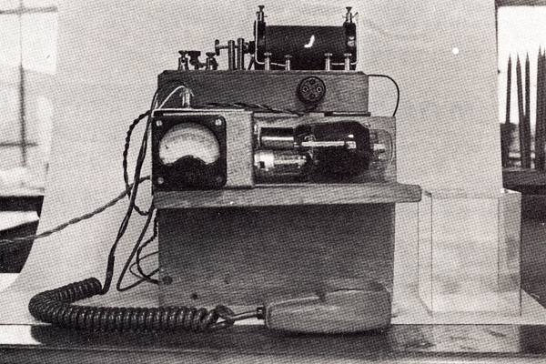
The transmitter amplifier. The 6L6G valve is mounted horizontally behind the ECC83. Above the 6L6G is a 2-way socket to which the arc lamp connects. The spark coil for striking the arc is at the top. The spark coil output connects to the two outside terminals of the four terminals immediately in front of it. Spark gaps are then formed, as shown in Fig. 4.
Striking the Arc
At least 1,000 Volts are required to strike the arc and several methods may be employed to achieve this. A pulse transformer and rapid switch-off choke circuits were under consideration when the arc was in the early stages of experiment. But to get things going the induction spark coil shown above the 6L6G in the photograph of the transmitter amplifier was used. To make the circuit safe and enclosed the spark coil is used with a Perspex cover (not shown).
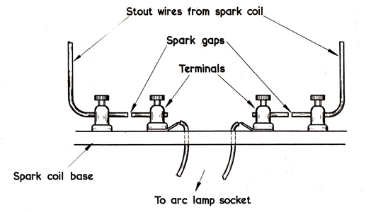
Fig. 4. Detail showing how a spark gap is inserted in each connection from the spark coil to the arc lamp.
The spark coil secondary is taken to spark gaps between the two pairs of terminals. (See Fig. 4.) The other terminals of the spark gaps connect directly across the arc lamp via the 2-pin socket shown centrally below the spark coil. Hence no DC from the power supply flows through the coil.
The correct polarity for the spark is found by trial and error and the requisite pulse is provided by quickly flashing a low tension supply to the coil primary. In fact if the 6.3 Volt heater supply is used momentarily in the primary the polarity of the spark is bound to be correct long enough to strike the arc. Once struck the arc should be maintained at not more than 55mA. Less than this can be used by adjusting the 6L6G current but the arc will lose intensity thereby. The meter is useful as a warning in case the arc has not struck or goes out because unless steps are taken very soon the screen resistor of the 6L6G will become hot and the valve may be damaged.
The Receiver
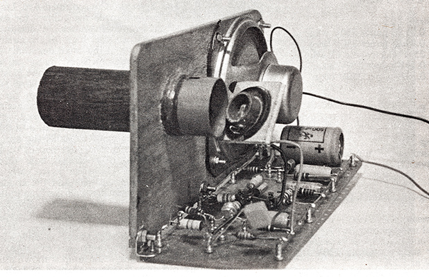
The receiver. The black tube projecting to the left shields the OCP71 from ambient light and also provides a mounting for the receiver lens. The OCP71 is fitted in the inside end of the tube, this being shown removed.
Several photocell types have been tried in the receiver but the only one more sensitive than the three OCP71s which were tested was an early OC7l with paint removed.
The original receiver circuit, shown in Fig. 2, was again designed for simple instruction and is not recommended for other purposes. Using an 18-way tagboard with two rows of tags, the components were soldered into the same positions as shown in the diagram. Although the circuit of Fig. 2 works well enough and is useful for demonstrations, it has the undesirable feature of allowing DC to flow through the speaker. Also, better negative feedback could be arranged.
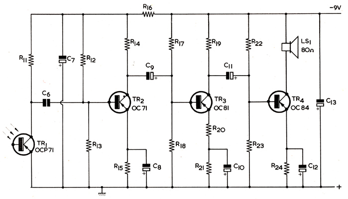
Fig. 2. A simple receiver as used for initial tests.
Simple Receiver components list.
In view of these points the standard receiver, which is based on the Mullard OC81 design (see Fig. 3) has been used, and quite good quality signals have been received. Over short ranges of the order of hundreds of feet the frequency response has proved satisfactory up to 7 kHz and there is still some signal at 10 kHz. No doubt improvements could be made with attention to circuit details but in this case the main aim was distance.
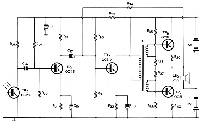
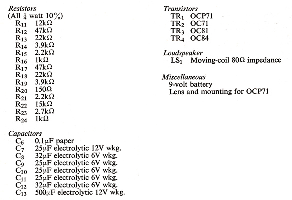
fig. 3. The standard receiver. This offers a better quality of reproduction.
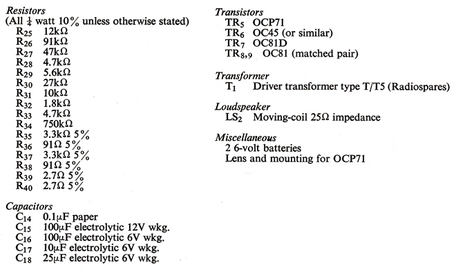
Standard Receiver components list.
The author did not find a gain control necessary in either receiver as the transmitter gain control gave sufficient control over modulation for his requirements. At close range, however, the receiver lens is removed so that the transmitter beam falls directly on to the OCP71. A gain control could be incorporated in the receiver if particularly desired.
Using a single lens system at the receiver similar to that at the transmitter, signals were received quite clearly at nearly a quarter of a mile in daylight. As the receiving OCP71 is well shielded in its tube from ambient light, the system is not likely to work a lot better at night. The OCP7l is fitted in the end cap of the tube. On top of the tube is a small hole so that the light beam can be adjusted to fall on the sensitive part of the cell at close ranges. At longer distances the beam has spread sufficiently for this to be unnecessary.
Some difficulty was experienced in aligning the beam to start with and early experiments were conducted after dark. But the difficulty of locating the receiver from the transmitter eventually led to daylight experiments being held, when the setting up was found to be much easier as the beam is quite visible in daylight. It is best to focus up in a long room on to a white card to get familiar with the sighting device and then transfer out of doors.
All the receiving equipment, part of the transmitting end and all the operating has been carried out by school pupils and the apparatus formed part of the exhibition held in Cambridge in September 1965, in connection with the British Association for the Advancement of Science annual meeting.
|