A Wide-Band Photophone
D Bollen The Radio Constructor, January, March & May, 1967.
Pre-Amplifier Construction
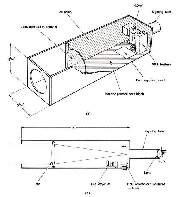
Fig. 12 (a). The manner in which the lens, photocell and pre-amplifier unit, and sighting tube are assembled. The dimensions for width and height are applicable to the 3in lens used by the author
(b). Side view of the assembly. The centre spigot of the B7G valveholder is soldered to a bush taken from a discarded potentiometer.
Recourse was again made to that useful material, hardboard, in the construction of the receiver. See Fig. 12. Undoubtedly an aluminium box would be better, but hardboard allows quick fabrication of prototypes and can easily be made light-tight. The box also forms the lens tube or collimator.
The pre-amplifier is constructed on a small Paxolin panel mounted, together with the photocell, at one end of the collimator. A useful feature of the 90AV is that its transparent red cathode material is deposited on the glass of the photocell body and a small sighting tube, with lens taken from an old box camera, was arranged to look through the photocathode. This turned out to be something of a refinement as optical alignment of receiver to transmitter was not critical and could be done at hip-height with a quick scan in the general direction of the Photophone transmitter. It is, however, useful at extreme ranges for placing the distant light source on the most sensitive area of the photo-cathode. The portion of the pre-amplifier box forward of the lens acts as a hood to prevent direct sunlight falling on the photocell, and it may be furnished with grooves to take colour filters, if required.
The receiver lens was taken from a reading glass, and is of 3in diameter. The advantage of a large lens is that it collects more light than a small one. The lens is mounted so as to throw a sharply focused image of the distant light source on to the photocell cathode.
As the input impedance of the pre-amplifier is high, it is susceptible to interference and screening was found to be necessary. This was quickly expedited by covering the interior of the box, aft of the lens, with aluminium foil, which was earthed in contact with the valve base mounting bush. Although the pre-amplifier could have been fitted with supply leads, it was decided to mount a small battery inside the box. This is particularly useful when the pre-amplifier unit is used in conjunction with a valve amplifier, since it gives no hum and no special power supply is required. The interior of the box should be painted matt black to cut down unwanted glare, and a lid with a light-tight ridge can be fabricated, also from hardboard.
Portable Amplifier
Hi-Fi headphones can give exceptionally good reproduction with a low power output, and they are light in weight. There are no baffle problems, with the result that such phones tend to flatter any signal fed to them. It was, therefore, decided to use phones with the amplifier circuit of Fig. 13.
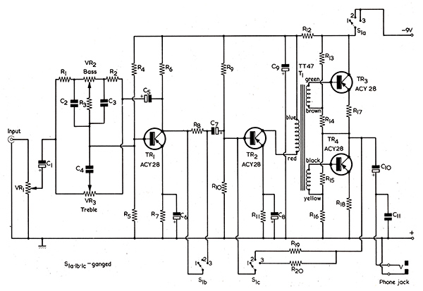
Fig. 13. The circuit of the portable audio amplifier. This follows the pre-amplifier of Fig. 11 and can feed headphones or a small loudspeaker.
For those who consider that headphones are out-moded, or are inconvenient to use, the amplifier will also power a small speaker purely for communication purposes.
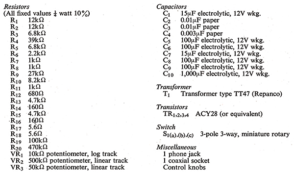
Portable amplifier components list
In Fig. 13 a tone network is provided which gives 10dB of bass cut and 10dB of boost, and the same amount of treble cut and boost. For a short range quality signal, say across a street, the controls can be employed to give a balance determined by individual preference. With long range communication the treble control can be backed off to cut down background noise, and the controls set for optimum clarity. If there is interference from street lamps, the bass control setting can be altered to drop the response at 50 Hz. The three position switch, S1 (a), (b,), (c), serves as an on-off switch and gives two gain settings. In position 2 R19, which is of a fairly low value, is brought into circuit and provides enough negative feedback for a linear response, whilst R8 serves to swamp out the diode effect of the base emitter junction of TR2. In position 3, R8 is short-circuited, and a different feedback resistor, R20, is substituted, giving high gain at long ranges.
The characteristics of the amplifier are as follows: With the switch in position 2 and tone controls flat the response is 50 Hz to 20 kHz ±1dB; and with maximum bass and treble cut, 400 Hz to 3 kHz. With the switch in position 3 gain is increased by 20dB, giving 700 Hz to 5 kHz ±2dB with controls flat, and 1 kHz to 3 kHz with full treble and bass cut. So, the first position gives a wide band characteristic, and the second will furnish narrow band, high gain working.
The DC resistance of the phones used with the original was 500Ω, but the amplifier will tolerate a variety of loads and may even be used with a 15Ω speaker at low levels. The main criterion of the amplifier was that it should reproduce both a 100 Hz and a 10 kHz square waveform without seriously degrading them, and this it did. There was a small amount of overshoot present on the 10 kHz waveform but the rise time was good, and full bass boost would almost compensate for the slight top arid bottom slope on the 100 Hz waveform.
Construction could take many forms. The prototype portable amplifier consisted of two small panels, one containing all the components associated with TR2, TR3, and TR4, and the other those associated with TR1. Both panels were mounted in a small plastic box, together with battery, switch, tone controls and volume controls.
Overall Results
To give some idea of the sensitivity of the receiver, a fly or other small insect, such as a midge, can be located at a distance of up to 12ft by the action of daylight reflected from its rapidly beating wings, causing a note to be heard. If the receiver lens is removed reception is possible at 150 yards, with nothing interposed between the photocell and a single 20 Watt fluorescent tube.

The appearance of a 5 kHz square wave after passing through the entire Photophone transmit-receive system, including all the associated amplifiers.
The photograph above shows a 5 kc/s square wave which was transmitted over the system, having passed through transmitter compensation network, pre-amplifier, power amplifier, fluorescent tube, receiving photocell, photocell pre-amplifier and the portable amplifier just described. Although there is a fair amount of rise and fall time evident the overshoot is small, despite some pre-emphasis on transmit.
Regarding susceptibility to weather conditions, the Photophone will transmit through rain, but not, of course, through thick fog. Four hundred yards is not a short distance when one has to keep walking it there and back, as the writer has come to learn! Many miniature radio control receivers do not offer a range greatly in excess of this, and it can be considered a useful distance for all sorts of applications. The effect of strong sunlight only become apparent if the transmitter lamp is placed on a large whitewashed wall. The glare from the wall will cause a slight drop in received signal strength.
Although the fluorescent tube cannot compete with gallium arsenide diodes for bandwidth, it does offer the possibility of virtually unlimited transmitter power with a response of at least 20 Hz to 25 kHz, which is sufficient for audio purposes. Equally, with the state of the art, gallium arsenide diodes are of low power, requiring tight optical coupling, and are expensive. The equipment used with. the fluorescent tube is conventional enough for much of it to be already on hand to the amateur constructor, and the tubes are not costly. If 50 to 100 Watt power amplifiers are available, two 8ft 85 Watt tubes could be employed to give a total light output of not less than 13,000 lumens, 13 times greater than a single 20 Watt tube, and approximately equal to a filament lamp of 750 Watts. With lens-less receivers, and a 15 Watt transmitter amplifier, reception could take place anywhere within a minimum area bounded by a circle of 150 yards radius, assuming no light-proof obstacles in the way. The equipment could then serve as an unobtrusive, licence-free paging system in large halls and open areas such as sports grounds.
|