Modulated-Light Transmitter and Receiver
M J Banthorpe The Radio Constructor, September, 1964.
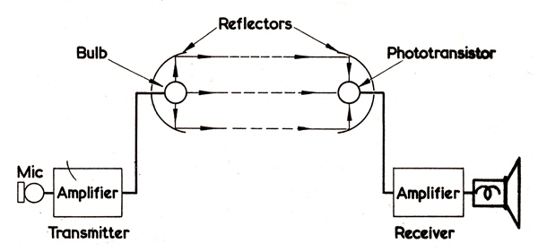
Fig. 1. The essentials of a light-modulated communication system.
Another successful modulated-light system
This article gives details of a modulated-light transmitter and receiver which was constructed by the author for experimental purposes. The general principle of operation is shown, in block diagram form, in Fig. 1.
The Transmitter
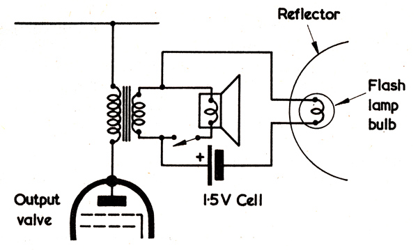
Fig. 2. Coupling the transmitting lamp to the output stage of the microphone amplifier.
A 3 to 5 Watt amplifier, or the output stage of a domestic valve radio (with the input fed to the gram sockets with possibly an extra stage of pre-amplification), is used to amplify the signal from a crystal microphone. The speaker is disconnected from the secondary of the output transformer and, in its place, is connected a battery and a 2.5 Volt flashlamp bulb mounted in a reflector. (See Fig. 2.) A car headlamp reflector is suitable for this purpose. Care should be taken not to use the amplifier without either the speaker or bulb connected, as this may cause excessive voltages to appear across the primary of the output transformer.
The Receiver
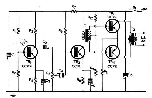
An OCP71 phototransistor was chosen as the photo-sensitive element because of its high sensitivity, rapid response and general availability. The circuit of the receiver is shown in Fig. 3.
.
.
The OCP7l phototransistor is mounted in a reflector similar to that used at the transmitter. The circuit consists of the phototransistor stage followed by a conventional 3-transistor 250mW amplifier. If desired, a 250Ω earpiece may be substituted for the primary winding of the driver transformer, T1, and the push-pull output stage omitted.
Operation
The signal voltage in the secondary winding of the output transformer at the transmitter causes the light output of the bulb to fluctuate accordingly. The light fluctuations are sensed by the phototransistor and converted back to sound signals. Since the filament of the bulb does not cool down instantaneously when it is not receiving current, signals above 2 to 3 kHz cannot be transmitted. Some bulbs work better in this respect than others and it is best to experiment with several types to find that which is most satisfactory. The quality of reproduction, although poor, permits the transmission of intelligible speech. The two reflectors must be in line with each other, and the positions of the bulb and phototransistor should be adjusted for maximum response.
Intelligible speech can be obtained at a range of 15 to 20ft. Greater ranges can be obtained by the use of higher output from the amplifier to the bulb.
|