G8LSD Laser Communications -
Main Equipment
G8LSD
e-mail allan@r-type.org
This thumbnail sketch describes the MkII version developed 1997-2001. The design aim was primarily for DX communication by keying an 800 Hz tone, but provision of PWM audio enables a wider range of experiments to be conducted. When we formed the group we all decided to adopt the 488 Hz tone chosen by G0MRF as it avoided all mains harmonics. Consequently the small tone generator was replaced by an equally simple design from David.
NB In all of this article it should be remembered that class IIIa lasers are used. The beam must never be looked into with the naked eye or a telescope. It is strongly advocated that beam expanders are used on all laser sources to reduce the power density to safe values. Even in these cases a telescope can recombine the beam to damaging intensity. For local testing, use a diffuse reflecting plate to focus the telescope onto and/or a neutral density filter.
The original design used a 10mW HeNe gas laser. The optical bed was over 1M in length and prone to slight sag, even though well braced. The laser beam passed through a Bragg modulator and onto a 50 times beam expander with a 50 mm aperture. The laser took 6.5 mA at 2.25 kV and the encapsulated power supply was driven from 240 Volts, but in the field, driven from an inverter, it lasted only a few minutes before failing. The modulator needed several watts of 80 MHz to operate and ran from a 28 V supply. Operating from home the performance had been good with signals heard returning from a diffuse reflector at some 200 M from the laser.
The MkII is based on commercial laser module from RS. The module is rated at 3 mW at 670 nM and operates from a -12 V supply. The modulation can be TTL for data or just 0.5 V pk-pk for analogue modulation. The maximum modulation depth with a digital signal is 90%. The essential fact about semiconductor lasers is that they are always on the edge of self destruction. The operating conditions have to be exact and spikes will destroy them. Modulation should be applied to a parallel or shunt modulator. The basic diode housings normally have a reference diode as well as a laser diode. This is to facilitate a feedback loop to control the laser output. The laser cavity is only a few microns across and whilst the few milliwatts dissipated is small, the power density is vast. Good heatsinking is essential, especially with diodes operating with output powers of 5 mW or greater.
Experiments had originally been based around the Scandinavian suggestions of 25 kHz SSB. Further thought, when the experiments were not as expected, tended to suggest that as the laser frequency was not being modulated, but could be treated as a straight amplitude modulation of the beam intensity a base band approach would be better. Additionally, the detection has to take place directly with no possibility of amplification of the incoming light frequency.
The detectors (Burr-Brown OPT series) are most sensitive near to DC and the wider the bandwidth the greater the noise to be dealt with as always. The cheap OPT101P was tried with success, and after using the OPT210 (high bandwidth) it was decided to use the OPT211 as it had the lowest noise. At base band, with greater sensitivity, the overall equipment could be a sensitive audio amplifier for receive.
The high impedance front end mandated a sealed box and good electrical isolation. A die cast box provided most of the screening, and only a small hole in the lid just large enough for the 2.25 mm square sensor to be visible has been made. The aluminium tube has an outside diameter of 1 1/4 inches to suit standard telescope eyepiece sizes. Internally it is painted matt black to absorb off axis light. To further secure good performance the OPT211 sensor and transconductance amplifer is coupled to an SSM2017 ultra low noise audio pre-amplifier. This device was designed for professional audio applications and has a quoted noise figure of 1.5 dB. In this present application the 13.8 V source voltage is converted in the head to + - 12 V by an isolating DC-DC converter. The signal output is AC coupled. To prevent massive overload to the SSM2017 a pair of back to back germanium diodes are placed interstage. It should be noted that the OPT211 will deliver an 18 Volt pk-pk squarewave with even moderate illumination levels. In use, with sensitive audio amplifier following the head, the background noise with the head tube covered by a black plastic cap is almost inaudiable. In starlight the head generates noticable background noise, suggesting that the head itself is adequately quiet. The leads to the receiver proper are all co-axial.
The output noise from extraneous light input will fall into the passband from all colours of input light. To excluse this source of noise requires a narrow optical filter. For the HeNe line at 632.8 nM a 2 nM filter is practical at a cost of £70.00 or so. But for the systems using semiconductor lasers the frequency spread around 670 nM can be considerable. The 50 nM wide filters are available but at present the choice has been made to operate at dusk as a means of reducing extraneous light pollution.
To capitalise on the low noise of the OPT211 the feedback loop had a 10 MOhm resistor in it. This lowered the bandwidth and up to 40 MOhm could have been used. I was aiming for a bandwidth of approximately 12 KHz.
From the original HeNe experiments I was certain that PWM audio would give the greatest punch. For the MkII a moving coil microphone is fed to a pre-amplifier consisting of a 741 op-amp and an SL6270 VOGAD amplifier. This gives a sensibly constant volume for the input to the modulator. PWM is sensitive to over modulation.
The Pulse Width Modulation is derived from a 566 waveform generator and LM393 op amp chip. The ramp voltage is set via a preset pot and the frequency also adjusted when setting up. The basic carrier frequency is approximately 8 kHz. The audio from the pre-amplifier is shaped in a Maplin SSB filter kit. The specification of 270 - 2700 Hz at the 6 dB points is achieved. In this way the carrier is safely above twice the highest frequency components contained in the audio stream. The output from the PWM source is fed into the driver circuit.
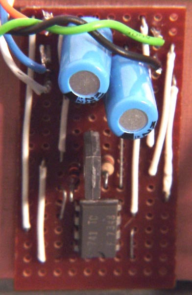
To provide the TTL signals for the laser a driver stage has been incorporated. This uses a 741 op-amp and a BD135 driver stage. All modulation inputs are passed trough this driver before being applied to the laser module.
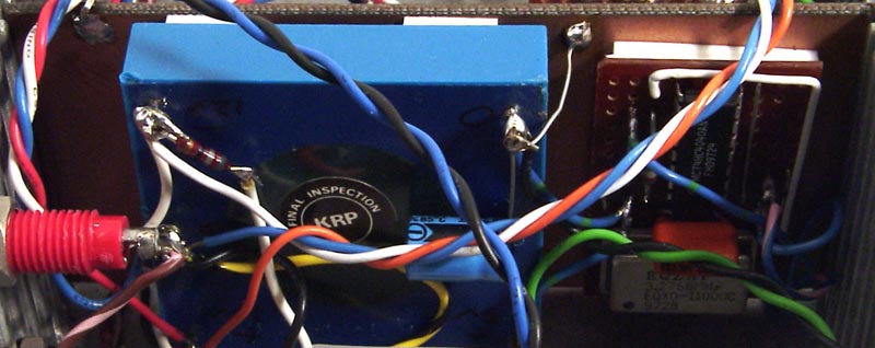
The laser module requires a -12 Volt supply. The equipment is run from standard 13.8 Volt supplies, and the transmitter has to derive all the required supplies. A DC-DC converter is used to produce dual rail supplies. The laser runs from the -12 Volt rail and the main circuits run from the + 12 Volt rail. As the DC-DC converter was available (ex equipment or junk box) I needed to generate 5 Volts from the raw input to power the converter. Over kill but the transmitter does not pick up mains hum.
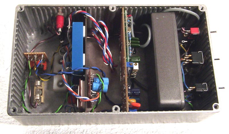
Finally the complete transmitter can be seen, with all modules installed within a sturdy die-cast case. The bottom contains a fixing to allow a standard photographic tripod adapter to be used. This fixing is for testing and demonstration purposes. In operation a stable platform with micro adjustments is required. The receiver head mounts into a Russian 4 1/2 reflector telescope with equatorial mount. The base is a steel tube of some 3 inches diameter fitted with heavy tripod base supports. Substantial. For the transmitter, the ex military tripod, used for the 10 GHz equipment is used. This can be held firmly to the ground, and on the top goes a heavy duty worm gear rotator. This rotator is driven by 5 phase stepper motor and is both robust and accurate.
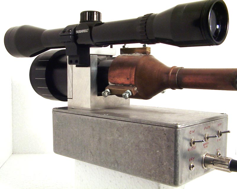
The final unit showing the controls.
Updated 18 OCT 2003