Crawley Laser Workshop 2004
By Allan Wyatt G8LSD, photographs by Chris Whitmarsh G0FDZ
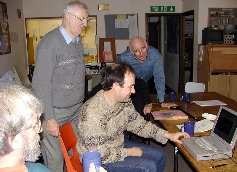
Argo and guests. From left to right: Allan G8LSD, Derek G3GRO, David G0MRF, Lech G3KAU, Dave G6KIE
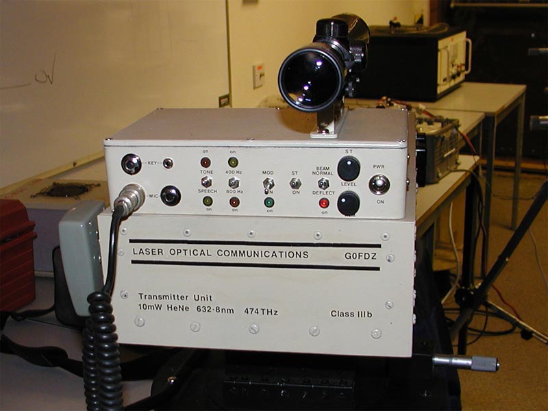
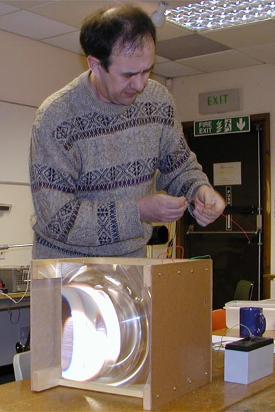
Putting us all to shame, Chris's new Laser transmitter engineered to perfection
Chris has been working on a new laser transmitter. The equipment, run from the mains, uses a 10 mW HeNe laser with a brick power supply. The beam is directed to the back of the case and a prism is used to send the light back towards the front. This ensures an adequate light path without excessive length. The latter always results in flexing of the base. The forward facing beam passes through a crystal modulator and on to a beam expander before leaving the case. A 28 Volt power supply is fixed to the right hand side wall and this powers the 80 Mhz modulator driver. In one small elegant case Chris has taken most of the optical equipment of a 1980s top-of-the-range typesetting machine. The top dicast box houses all of the electronics. A full article will follow.
New Horizons
All contacts to date have required a visual capture of a light source and aiming the equipment by eye onto the visible source. For over the horizon, cloud scatter and faster capture of a signal it is essential to be able to detect a non visible signal. This workshop was devoted to techniques that may achieve this goal.
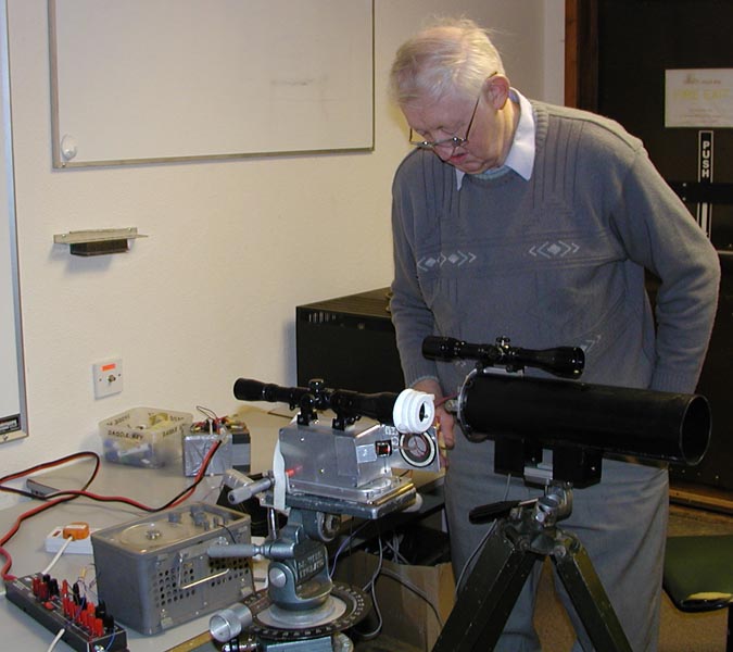
Derek G3GRO with transmitter modified for beam scanning
Derek and Lech had been looking into the potential of variable width beam scanning. This would enable a scanned beam to be swept up over a target site and once a signal was detected the scan width could be reduced until maximum signal was being received.
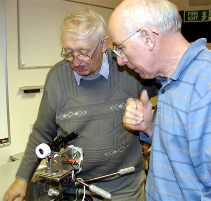
Derek and Dave with the Piezo scanner system
Derek demonstrated the piezoelectric scanner to make the laser scan over a variable angle of plus and minus 0.5 degree depending on the AC voltage applied to the transducer. The maximum potential applied for a one degree scan width was 10 Volts.

Piezoelectric scanner disc with actuator arm and mirror
A PCB arm was glued to the centre of the transducer and a fulcrum set to just outside the diameter of the Peizo device. The short end of the arm was shaped to 45 degrees and a small mirror attached.The picture shows a second mirror attached with Blutack as the first gave a fuzzy image. Front surface mirrors are on order for the final version.
Weak signal reception without visual indication of a signal
The first experimental set-up consisted of a two inch beam expanded signal being aimed through a doorway, some four metres distant and hitting a dark wooden door four metres down a corridor. This central table and corridor can be seen in the top picture. The door was angled so as to reflect all light onto the walls of the corridor and not back on a return path. The receiver consisted of a detector in a short collimating tube but devoid of any optics. Both transmitter and receiver were G8LSD's equipment. See Equipment This detector was angled so as to be aiming at the wall to the left side of the corridor. No direct path for any reflected signal existed when finally set-up. The minimum signal point was established by listening to the reflected signal and then turning the detector until the signal was only just present. At this point the receive output was coupled to the laptop running ARGO. The laptop is a basic Toshiba Satelite from 1998 running Windows 95, with an 800 x 600 pixel screen and a 200 MHz clock speed. The sound card is integral to the design.
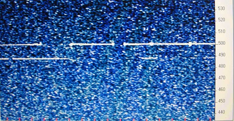
The first ARGO trace
A signal was present at 488 Hz as well as a strong signal at 500 Hz (a harmonic of the AC mains from a single dimmed room light).
Once capture on ARGO was achieved, the detector was rotated further to reduce the signal further. The room was darkened and when our eyes were dark adapted the room was scanned for reflections. None were seen in the main room. In the direction the detector was pointing there was no visible sign of a red reflection. ARGO was still able to copy a signal.
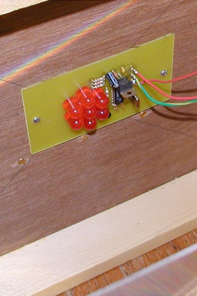
David with his LED source
David had modified his Freznel lens receiver to form a low power wide beam source. This uses an array of bright LED's modulated at the standard 488 Hz. The purpose of the source was to act as a beacon for receiver tests.

The LED source in action
The second experiment placed G0MRFs LED source off to the right of the far end of the corridor and pointing back to the dark wooded door that was set to just less than 45 degrees. A sheet of paper was placed over the LEDs to further reduce the light output in the direction of the door. With the room in total darkness the ARGO signal was still clear but no visible source was seen, not even a reflection of the door at the end of the corridor. This was much better than expected.
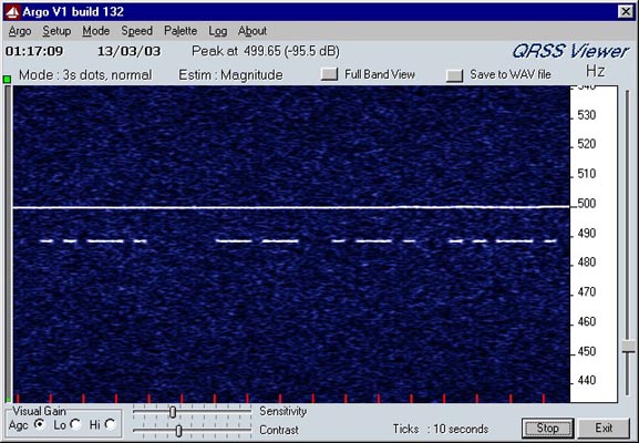
The final ARGO signal screen capture
From the trace above can be seen the 500 Hz trace from the low level room lighting, we needed some light to make the screen capture, and the 488 Hz signal trace. The value of adopting David's choice of 488 Hz for a signal tone now becomes self evident. The trace itself shows the beacon keyer repeating the main letters of its creators callsign.
With much thanks to the Crawley Radio Club for making available their club-house for the workshop.
Held on 6 March 2004