Modulated-Light Broadcast Transmitter
Douglas Letts The Radio Constructor, March, 1965.
The most ambitious modulated-light transmitter to date. A range of 150 yards in all directions is given by three 15 Watt mains lamps mounted on the roof!.
Editors Note
Over the last few years, we have published a number of articles on modulated-light systems, the first of these, Light Modulation by G5UJ, appearing in the February 1960 issue. This was followed by Light-Beam Transmitter-Receiver by J Emmett (April 1963), Speech-on-Light System for Communication by C. Morgan (January 1964) and Modulated-Light Transmitter and Receiver by M J Banthorpe (September 1964).
All the systems previously (described employed bulbs of around flash-lamp size for transmission. Our present contributor, who was inspired in particular by Mr Emmetts article, has gone a stage further and transmits modulated-light signals by way of three 15 Watt mains-type bulbs. The transmitting bulbs are not focused on to the receiver but radiate in all directions. It is merely necessary to aim the receiver phototransistor at the transmitting bulbs to pick up the signal, and ranges up to 150 yards have been achieved.
This article is aimed at the more experienced experimenter, who will be able to obtain and bring into use equipment of the type employed by our contributor. - Editor.
Thirteen years ago (1952) I was told that speech transmissions by a torch bulb couldnt be done. However, my eyes were opened by the article Light-Beam Transmitter-Receiver in The Radio Constructor for April 1963. I collected together a number of pieces of equipment including a tape recorder, an early Quad amplifier, as well as lamps, lenses, a gunsight and a number of other parts. When the installation was finished it worked far beyond my expectations.
The range in daylight was a circle of 100 Yards radius. Speech and music came through well. Even though the response was poor above 2 kHz, there was still something at these frequencies.
The Transmitter
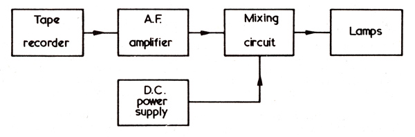
FIG. 1. Block diagram of the modulated-light transmitter.
Fig. 1 shows a block diagram of the transmitter.
The tape recorder feeds a signal to the Quad amplifier and the output of the amplifier is mixed with a steady current from a DC power supply. The combined currents supply the lamps.
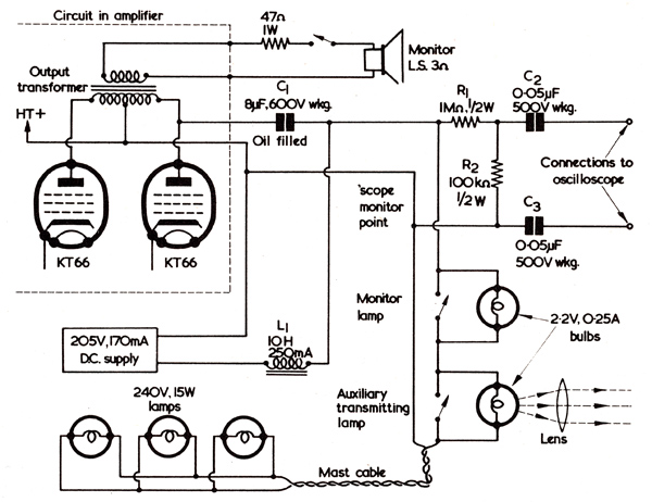
FIG. 2. The amplifier connections, mixer circuit and monitoring points at the transmitter.
Fig. 2 shows the connections to the Quad amplifier, the mixing circuit and the lamp circuit.
Connection is made to the centre tap of the KT66 push-pull output transformer and to one anode only. The normal loudspeaker output terminals of the amplifier are used to drive a monitor loudspeaker via a switch and attenuating resistance. The mixing circuit has two components, these being a heavy duty choke and a coupling capacitor.
The choke, L1 in Fig. 2, is rated 10 Henries at 250mA, and is sufficiently large to pass the lamp currents and allow such low frequencies as reach the output stage to modulate the lamps. Low frequencies are attenuated in the amplifier by operating it with the bass control at minimum and the treble control at maximum. This compensates for the thermal lag or inertia of the lamps.
The coupling capacitor, C1 of Fig. 2, has to be large enough to fulfill two requirements. It must pass low frequency signals and it must not resonate with L1 in the signal frequency range. Three small electrolytic capacitors have been destroyed in this position, presumably by the high AF lamp current. A 8μF, 600V working, oil-filled capacitor is now used and has given no trouble.
The DC supply provides 205 Volts at about 170mA to the lamps. The output leads of this power supply are isolated from its chassis. The lamps are under-run by the DC supply, and there have been no lamp failures in 100 hours of transmitting time.
Two other means of monitoring are used as well as the loudspeaker. These are given by oscilloscope-monitoring terminals, each having 0.05μF isolating capacitors in series, and by two 2.2 Volt, 0.25 Amp, Lens End torch bulbs. The latter are Ever Ready Cat. No. 2225.
The oscilloscopes main function is to check on amplifier overloading. Over-modulation occurs when the modulating voltage is sufficient to reverse the sign of the lamp current. In the present set-up, amplifier overloading occurs before over-modulation.
The torch bulbs in series with the lamp feed provide visible evidence that the roof lamps are on and being modulated. It is not necessary to go out into the open and get a stiff neck by staring skywards at the lamp mast, since a check on modulation quality is readily made by directing the portable light receiver at the monitor lamp. One of the bulbs is used as an auxiliary transmitting lamp. This bulb and a lens is mounted on a board with Plasticine. The lens position is adjusted to give a narrow beam and it is directed where required from the transmitter room window. The lens has a diameter of 1.25in and a focal length of about 4in. Both torch bulbs have bypass switches. These allow the low voltage lamps to be out of circuit at switch-on and thus not subject to the current surge as HT is applied to cold mains bulbs.
The auxiliary transmitting lamp, with its lens, has a greater range than the main lamps but it is very directional. It is currently being used for experiments with filters.
The main transmitting lamps are mounted upright on a roof mast, and spaced 120 degrees apart without reflectors. Three 240 Volt, 15 Watt, plain glass types are employed. It was found that plain glass lamps gave a noticeably stronger signal than pearl lamps of the same rating. A number of small lamps are used in preference to a single lamp of equivalent power on the assumption that the thermal lag of low wattage lamps is smaller than that of high wattage lamps of the same voltage rating. However, no measurements have yet been made to confirm this.
The Receiver
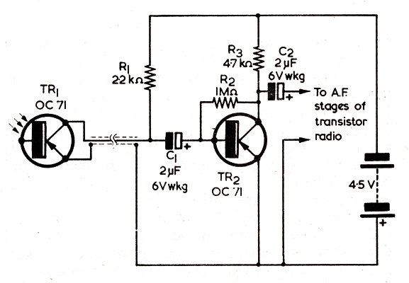
FIG. 3. The pre-amplifier at the receiver. The resistors are all half or quarter Watt types. For working at night c1 should be reduced to 0.1μF.
The heart of the portable light receiver is an OCP7l. (Initially Mullard painted sub-standard OCP71s black and sold them as OC71s. Experimenters in the 1960s used OC71s with the paint scraped off as a cheaper option to the OCP71 - G8LSD.)
The OCP71 is mounted on its side in a bed of Plasticine at one end of a cardboard tube. A lens, similar to that used with the auxiliary transmitter bulb, is fitted in a valve screening can which makes a push fit in the cardboard tube. This serves as a focusing draw-tube. The lens and OCP71 assembly was strapped with Cellotape and Plasticine to an ex-Barracuda optical gunsight, but any small telescope could be used. A few yards of light, flexible screened lead connects the OCP71 to a pre-amplifier mounted on the back of a portable transistor superhet radio, the pre-amplifier output being connected to the radios audio amplifier circuit. The OCP71 and pre-amplifier circuit is given in Fig. 3.
The circuit of Fig. 3 is crude, but it works. For bright daylight, C1 has a value of 2μF as shown, and the range is 100 yards, extending to 150 yards at dusk. For night use, better results are given by reducing C1 to 0.1μF. The night range is 150 yards.
Much of the success of this receiver I attribute to careful focusing of the receiver lens. The beam width is just under one degree of arc at each of two sensitive spots on the emitter side of the OCP71. These spots are a little over one degree apart on this particular transistor. One is more sensitive than the other. With such high directivity of the receiver it is impossible to use it without the gunsight except at very short range.
Testing
For test purposes a short tape loop is used on the tape recorder. On one track is an interrupted 600 Hz tone, and on the other a short announcement: 'You are listening to a transmission by modulated light'. For demonstration purposes a reel with a more varied programme is used. It is found advantageous to avoid programme material of variable strength and to keep the modulation near the maximum as the lamp-light signal output increases at a greater rate than the modulation voltage. A related effect is especially noticeable when using the interrupted-tone test-loop. Although each tone burst is of constant amplitude, it is received as a tone burst with a build-up at the start.
I call this transmitter a broadcast transmitter to distinguish it from directional transmitters for use in point-to-point working. Time and money allowing, I hope to make improvements to the range and modulation characteristics. Happily, there is no shortage of ideas or paper to set them down, and my thanks go to the author of the article that originally inspired me.
|